Following up on my previous post of the Cheap and Easy series, I’m going to show you how you can control 8 relay channels for about 25 bucks and in about 30 minutes. If you’re not familiar with Home Assistant or ESPHome, check out my previous post.
In this project, I use a Wemos D1 Mini as the wifi enable the controller to interface with the relay module using the IO expansion shield. The magic of this setup is using the IO module and soldering it directly onto the relay board. This eliminates the narly mess you see you when would typically have 8 channels of relays. As a bonus, since you are only using 8 of the available 16 channels on the IO module, you could use the remaining 8 IO to do all sorts of other things.
Shopping list:
- Wemos D1 Mini – The Wemos D1 Mini is an ESP8266 based microcontroller that will handle the heavy lifting of WiFi and communicating to your Home Assistant instance [ Amazon, 3 Pack, Amazon, 5 Pack ]
- MCP23017 IO Expansion Module – This is what you will use to allow you to drive all 8 relay channels with minimal effort [ Amazon ]
- 8 Channel Relay Board – I added the DHT to get temperature and humidity data [ Amazon ]
- Assorted Dupont Jumpers – Always have a bunch of these handy, they have a tendency to disappear and get used up in projects. [ Amazon ]OPTIONAL: If you want to control 12v or 24v loads
- Appropriate DC power supply for your loads – This will vary on what you are trying to control, links to some options. [ Amazon 12v 5A | Amazon 24v 3A ]
- LM2596S DC-DC power regulator – It converts garage door’s 12V DC to 5V DC for the Wemos or use a microUSB cable. [ Amazon ]
- Soldering Iron Kit – It’s likely that you already have this if you’ve been DIYing for a while [ Amazon ]
Installation is cake
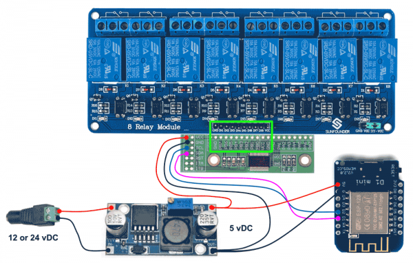
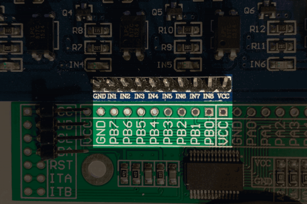
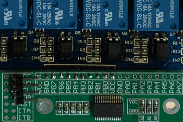
You will need to provide 5v DC power to power the system. To get started, you will want to place the IO module over the pins of the relay module. Make sure to line these up correctly as I’ve indicated below. If you don’t, it’s a big pain to remove it and put it back on correctly, especially if you’ve soldered it in place. Ask me how I know.
The IO module will have a total of 4 wires connected to it: two for +5v and GND from the power supply, and two for the I2C (SDA and SCL) from the Wemos.
The IO module will have a total of 4 wires connected to it: two for +5v and GND from the power supply, and two for the I2C (SDA and SCL) from the Wemos.
That’s it!
Since it’s likely that you will want to switch/power things that are of higher voltage than the 5v rail you need to power the Wemos, I’ve included the 12v and 24v optional power supplies. Be sure that you do not connect any of these higher voltages to any of the logic pins on the Wemos or the IO, only connect them to the relay output terminals.
ESPHome config
I created the 8 channels as output switches and for the time being omitted the remaining 8 channels which can be configured as inputs or outputs. I created a new device, named it esphome_relay_board using a D1 mini board with the following config:
|
1 2 3 4 5 6 7 8 9 10 11 12 13 14 15 16 17 18 19 20 21 22 23 24 25 26 27 28 29 30 31 32 33 34 35 36 37 38 39 40 41 42 43 44 45 46 47 48 49 50 51 52 53 54 55 56 57 58 59 60 61 62 63 64 65 66 67 68 69 70 71 72 73 74 75 76 77 78 79 80 81 82 83 84 85 86 87 88 89 90 91 92 93 94 95 96 97 98 99 100 101 |
esphome: name: esphome_relay_board platform: ESP8266 board: d1_mini wifi: ssid: 'insert' password: 'your_own' fast_connect: on api: ota: web_server: port: 80 logger: i2c: sda: D1 scl: D2 scan: True mcp23017: - id: 'mcp23017_hub' address: 0x20 switch: - platform: restart name: "Relay Channel Board REBOOT" - platform: gpio name: relay_channel_1 icon: mdi:electric-switch pin: mcp23xxx: mcp23017_hub number: 15 mode: OUTPUT inverted: True - platform: gpio name: relay_channel_2 icon: mdi:electric-switch pin: mcp23xxx: mcp23017_hub number: 14 mode: OUTPUT inverted: True - platform: gpio name: relay_channel_3 icon: mdi:electric-switch pin: mcp23xxx: mcp23017_hub number: 13 mode: OUTPUT inverted: True - platform: gpio name: relay_channel_4 icon: mdi:electric-switch pin: mcp23xxx: mcp23017_hub number: 12 mode: OUTPUT inverted: True - platform: gpio name: relay_channel_5 icon: mdi:electric-switch pin: mcp23xxx: mcp23017_hub number: 11 mode: OUTPUT inverted: True - platform: gpio name: relay_channel_6 icon: mdi:electric-switch pin: mcp23xxx: mcp23017_hub number: 10 mode: OUTPUT inverted: True - platform: gpio name: relay_channel_7 icon: mdi:electric-switch pin: mcp23xxx: mcp23017_hub number: 9 mode: OUTPUT inverted: True - platform: gpio name: relay_channel_8 icon: mdi:electric-switch pin: mcp23xxx: mcp23017_hub number: 8 mode: OUTPUT inverted: True status_led: id: status_led pin: number: GPIO2 |
The components above include
- An I2C component to enable I2C communication
- A MCP23017 component for the IO module
- A switch restart component to reboot the Wemos
- A switch GPIO component for the relay
- A status LED component for indicating networking/error status.
Now can compile the firmware and flash it to your Wemos D1. Again, if you’re not familiar with how to do this, reference the videos linked above. Once it’s flashed, power cycle the device. Now you should be able to open the web GUI for the device by either going to it’s IP or going to http://esphome_relay_board.local in your browser, or whatever you named it. When the page loads up, you should test out the relay switches by hitting the button next to them.
Integration into Home Assistant
Now to integrate it into Home Assistant, you will need to go to configuration > integrations. Assuming you have discovery enabled, you will have a new ESPHome device, click configure and add it to your system. If you don’t have any existing conflicting entities, your entity names should match the ones I have. I’m using the following config for lovelace:
|
1 2 3 4 5 6 7 8 9 10 11 12 13 |
- type: entities title: Garage Relay Module + IO show_header_toggle: false entities: - switch.relay_channel_1 - switch.relay_channel_2 - switch.relay_channel_3 - switch.relay_channel_4 - switch.relay_channel_5 - switch.relay_channel_6 - switch.relay_channel_7 - switch.relay_channel_8 - switch.garage_relay_module_reboot |
This provides you with a simple switch list. Each icon shows you the state of the relay. And lastly, you get the reset switch to reset the ESP.
Would this setup work with all these components if I were to use this 16-channel relay board instead of the 8-channel? It doesn’t look like the pins from the expansion board will line up with the ones on the relay board.
https://www.amazon.com/Cp-Tree-Channel-Multiplex-Isolation-Tolerant/dp/B07QF6VNPL/
Very good tutorial. Thank you!
It would probably be easier to use two separate 8 channel boards with two IO modules if you need 16 channels
There’s a bug in the code:
i2c:
sda: D2
scl: D1
scan: True
D1 and D2 should be the other way around:
i2c:
sda: D1
scl: D2
scan: True
Awesome thanks for catching it!! Fixed.
I would imagine it wouldn’t line up. If you want easiest wiring option, do two multiples of the 8 channel setup. You’ll just have to change the address of the second MCP module with the onboard solder pads.
Hi! I think the commercial controllers are doing something more than a straight relay to control valves.
I get really bad water hammer when my valve gets turned off via my outdoor Z-wave switch. I tried borrowing my friend’s new Orbit controller, and amazingly the hammer is gone.
My suspicion is that the Orbit is soft powering off the valves. Perhaps some kind of RC circuit with a long time constant to slowly close the solenoid?
Not sure. From what I’ve seen a lot of the commercial ones use a valve, which are inherently slow. On the other hand, the solenoid you mentioned, is typically very fast as they operate in a linear motion driven by magnets.
My bad, I confused your article with another similar one I was reading which was geared towards a DIY irrigation controller
Hey, I just went through your tutorial and I have everything set up, but I’m not able to control the relay. The web server for the relay spins up fine and I am able to toggle the states for different channels, however that does not seem to have any effect. I do see in the logs that I2C devices were found and etc. I also checked to make sure the relay is getting proper voltage on it’s VCC pin using a voltmeter. It seems to be getting 5.4V so that should be fine. Any ideas of what I could do to trouble shoot this further?
Nice work, though, you have also forgot that ESPs run 3.3V on all their digital IO pins.
You need a 3.3V – 5V logic level converter (e.g. https://www.aliexpress.com/item/32771873030.html) not to ruin your ESP soon. Since you use i2c should use a bidirectional fast one.
I hope this helps in the stabilization of your projects!
Am ready to order the parts, but not sure about the comment from BBK on the voltage converter. Do I need that and how is it connected.
Thanks,
BobT: officially GPIOs are only supporting 3.3V (https://www.wemos.cc/en/latest/d1/d1_mini.html)
The Espressif ESP8266 datasheet, on page 19 defines also 3.6v and 12mA max current: https://www.espressif.com/sites/default/files/documentation/0a-esp8266ex_datasheet_en.pdf
Though, there are people who has tested it and it works with 5V, though, it highly depends on the hw implementation (“clones”, since Espressif releases their specifications based on which others are also manufacturing boards).
In this special case though, we could be lucky, since this relay board could be operated with isolated 3.3V for the I/O and giving 5V to the relays/transistors. Check the datasheet of the relay board, page 3:
https://www.handsontec.com/dataspecs/module/8Ch-relay.pdf
“It is sometimes possible to use this relay boards with 3.3V signals, if the JD-VCC (Relay Power) is provided from a +5V supply and the VCC to JD-VCC jumper is removed. That 5V relay supply could be totally isolated from the 3.3V device, or have a common ground if opto-isolation is not needed. If used with isolated 3.3V signals, VCC (To the input of the opto-isolator, next to the IN pins) should be connected to the 3.3V device’s +3.3V supply.”
Do not misunderstand me, I am not saying that the connection presented by D Khaz is not working, or bad, but according to the datasheets, it is not compliant. I am just building an automated sprinkler solution based on esp8266 and this type of relays, and would want it to be on the safe side, have it work reliable.
I would also be curious about D Khaz’s opinion on the topic too.
BBK, Thanks for the quick response. I agree with the 3.3v for the I/O, but I noticed that the interface came in various physical configurations. I found one from AliExpress that matched the physical configuration in the write-up: https://www.aliexpress.com/item/32964452209.html?spm=a2g0s.8937460.0.0.1de92e0e8UAMFZ but could not find any electrical specs.
Another version of the MCP23017 IO indicates it is compatible with both 3.3v and 5V levels: https://www.aliexpress.com/item/32964452209.html?spm=a2g0s.8937460.0.0.1de92e0e8UAMFZ but has a different physical configuration.
I was unable to find the specifications on the relay board. If you have them please send me a link.
Thanks
Bob
I drive 5v relays with it so I know it works for my application, but I’m not sure about 3.3v
Yes, it would definitely work. You should also check out this form factor of the MCP chip as it might better alight to the 16 channel relay: https://amzn.to/2PN55zc
DK, Just finished the project and it is working. Have two questions, I would like to configure one of the unused pins PA0 – PA7 as binary input. Added this sample code from HA:
# Example configuration.yaml entry
binary_sensor:
– platform: mcp23017
i2c_address: 0x20
pins:
0: PIR Office
1: PIR Bedroom
and received an error message:
Platform not found: ‘binary_sensor.mcp23017’.
platform: mcp23017
i2c_address: 32
pins:
0: PIR Office
1: PIR Bedroom
Any suggestion on how to add a binary sensor?
Also on power up/reset all the relays are triggered . Can this be turned off?
Thanks
Found Answer to input pin: https://esphome.io/components/mcp230xx.html
Yea, it’s easily configurable it just requires to use the appropriate syntax for that module
Hola buenas tardes, estaba viendo tu proyecto y me interesaría poder modificarlo para su integración con domoticz. El problema es que no puedo visualizar tu código me lo podrías pasar?
Gracias
Nahuel Baglietto
Hello good afternoon, I was looking at your project and I would be interested in modifying it for integration with domoticz. The problem is that I cannot visualize your code, could you provide me with the code?
Thanks
Nahuel Baglietto
Hello Dmitriy, I like your project and I would be interested to be able to modify it for its integration with domoticz and google assistant. Could you provide me with the code? since on the page I do not see it.
Thanks a lot
Nahuel Baglietto
Good that you figure out the pin.
To solve the triggering at startup, look at the ‘restore_mode’ configuration on https://esphome.io/components/switch/gpio.html
Hi Carlos, there is no code, just configuration. The project itself is on GitHub.
Tienes una direccion en github ? me podrias pasar la url
Muchas gracias
Nahuel Baglietto
Ok I apologize, I had not realized that it was an option with a different firmware from the wemos d1 mini. I was thinking about something else when I read ESPHome I imagined it was a server like domoticz or openHAB or Home-Assistant.io.
Thank you and sorry for the misunderstanding
Hey DK
I like your writeup, the yaml configuration is empty though…
If you run HASSos, you can install esphome as an add on with only a few clicks. In my setup, I run both home assistant and esphome using docker containers
Thanks for letting me know! It’s now fixed. It was an issue with my syntax highlighter plugin and I’ve now migrated to https://github.com/urvanov-ru/crayon-syntax-highlighter
Carlos, My YAML configuration code may not have been displayed on the site when you looked at it. Check again and see if it makes a bit more sense now.
Ok ahora si se ve gracias
De nada
Hi,
Thanks for great solution. I have implemented it but have some issue with turning on relays during reset. I have tried all ‘restore_mode’ from GPIO config but still the same response. Have You managed to figure out this issue? Below my code, maybe I am missing something? Will be grateful for some tips.
esphome:
name: przekazniki_2
platform: ESP8266
board: d1_mini
wifi:
ssid: xxx
password: xxx
# Enable logging
logger:
# Enable Home Assistant API
api:
password: xxx
ota:
password: xxx
i2c:
sda: D1
scl: D2
scan: False
mcp23017:
– id: ‘mcp23xxx_hub4’
address: 0x25
switch:
– platform: restart
name: “Restart przekaźniki_2 dół”
#mcp23xxx_hub4
– platform: gpio
restore_mode: ALWAYS_OFF
pin:
mcp23xxx: mcp23xxx_hub4
number: 8
mode: OUTPUT
inverted: True
id: relay49
– platform: template
name: relay_channel_49
icon: mdi:electric-switch
turn_on_action:
– switch.turn_on: relay49
– delay: 500ms
– switch.turn_off: relay49
turn_off_action:
– switch.turn_off: relay49
and so on for other relays, I have many of them…
Try thinking through it from start to finish. Are your relays high trigger or low trigger? If they are low-trigger you can activate the pull-up resistors inside the mcp23017. Alternatively, if they are high-trigger you can add external pull-down resistors. You can also try looking at the ESPHome logs when it’s booting to see if it’s doing anything odd to cause it to turn on momentarily, although restore_mode should take care of that.
My idea of configuration is to use relay as “Momentary switch”, see this in ESPhome description below. It activates relay for period of 500ms, like an impulse signal to activate other things I have in my electrical box.
https://esphome.io/components/switch/gpio.html
Other connections and configuration are exactly as in Your description. Restore mode reconfiguration unfortunately does not help anything. I will gather logs for further discussion.
It took some time but finally I made logs. First part from booting esp and later on with software triggered restart. In addition I have added to code “Restore Mode: Always OFF” to indicate that it does not help anything with triggering shortly all relays during booting.
https://pastebin.com/xWmaq3fB
Hello, soo i got all this working, But ive been trying to add the relays to the home automation part in home assistant, but the relays dont show up, but yet i can add them to lovelace dashboard
There is no home automation part in Home Assistant. If you can add them to your dashboard, then everything is working as it should. You can also check under your ESPHome device in the Integrations section.
Are you trying to create an automation controlling one of the relays?
I went to modify some of my code and noticed the following note:
‘mcp23017:’ has been removed from the pin schema in 1.17.0, please use ‘mcp23xxx:’.
Any suggestions on what to do next??
Thanks,
Bob T
The schema (name of the sensors) has changed since I originally wrote this code a few years ago. I’ll try to post an update.
Thinks, what i tried and it worked was simply replaced “mcp23017” with “mcp23xxx” and the message went away and everything seems to be working ok.