Last updated on August 31, 2024
About a year ago I started a project to figure out if I can add lighting to my hundred-year-old house without too much work. Famous last words. Looking back at it, hiring an electrician would have been faster and maybe cheaper, but I wouldn’t have learned anything. This is a summary of the journey I took through buying parts, programming ESPs, and ultimately, making my first PCB.
Humble benginnings
Initially, I wanted to see how I could scale the ability of controlling LED lights. Analog LED strip lights were about 7 bucks for 15 ft from China and recessed lights were about the same. More importantly, being that these lights are LEDs, they very efficient especially when driven and 60%-80% of their max rating. So I went online and ordered a dozen LED recessed lights, LED strips, and some COB LEDs which are inside of the recessed lights.
My plan was to hook the LEDs up to 24vDC and see how they worked. For the LED strips, it was easy as you can order them in 24v flavor. But the recessed lights are all powered by little LED drivers that are 110/220 to 24v. I first started by burning up a few of the COB LEDs to see what they could take. It turns out the larger COBs did fine with 24v but the smaller ones burned up. Driving two of the smaller ones in series worked fine.
Now I needed to control them
At this point, I had used and flashed a few H801‘s to control analog RGBW strips. While the H801 is nice little package, it had a habit of ringing at certain PWM frequencies. Combine that with the fact that it was using an ESP8266 software PWM to drive the FETs left room for improvement.
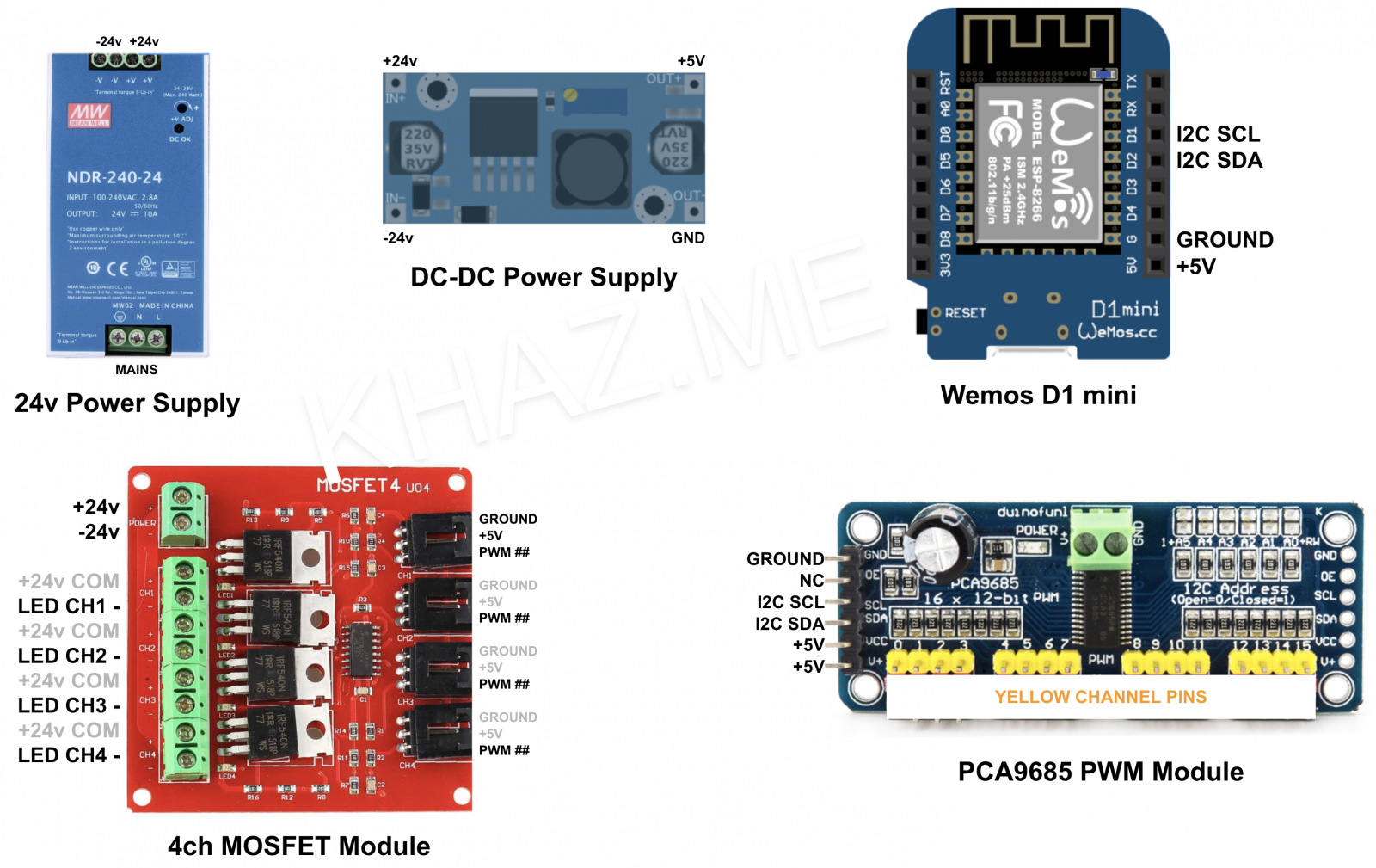
Since this was my first foray into controlling analog LEDs, I wanted to see what I could achieve from off-the-shelf components. The key was to drive the LED with a good PWM driver at a high enough frequency that made them work well. I already had a few dozen Wemos D1 Mini, but decided to try a servo controller for the PWM generator and tie it to a MOSFET. Here is the hardware I used:
- Controller – Wemos D1 Mini
- PWM – PCA9685
- MOSFET – 4ch module
- Power Supply – 24vDC 10A DIN Rail
- DC-DC converter – LM2596
To my surprise, this setup worked flawlessly on the workbench. For a few months, I used this in my garage to see if it was going to be short-lived, but it just kept working. Initially, I powered these via a bench power supply and later moved the setup over to the DIN Rail PS above. Keep in mind, your power supply should be sized for the load you plan on powering with some headroom.
Circuit Operation
Pulse Width Modulation allows you to control the brightness of the LEDs. The way that you control an LED’s brightness is by turning it ON and OFF, many times per second (this is called PWM frequency). The longer that the LED stays ON, compared to OFF, the brighter the LED will light (this is called PWM duty cycle). In this circuit, the PCA9685 is the PWM generator. For example, the Wemos D1 controller will tell the PCA9685 to turn on channel 1 at 50% duty cycle. The PCA will then pulse that channel at half ON and half OFF based on the frequency you’ve configured for the module. This pulse is an output from the PCA and is wired up to the gate pin of an N channel MOSFET. This device will then act as the switch that turns the LED on and off.
Wiring
The key thing to understand about the wiring is that the Wemos D1 mini and PCA9685 are not 24v tolerant. If you put 24v on them, you will release the magic blue smoke. So, just make sure before you turn it on, you double-check your wiring that you’re only run 5v to these devices.
One PCA9685 has 16 channels and each MOSFET module has 4 channels. This means you can go up to 4x MOSFET modules for one PCA9685. I have some channels that are running 4 and 6 recessed LEDs, and many that are running a single recessed LED. This gives you a lot of flexibility in how you wire your lights giving you much more control of your lights.
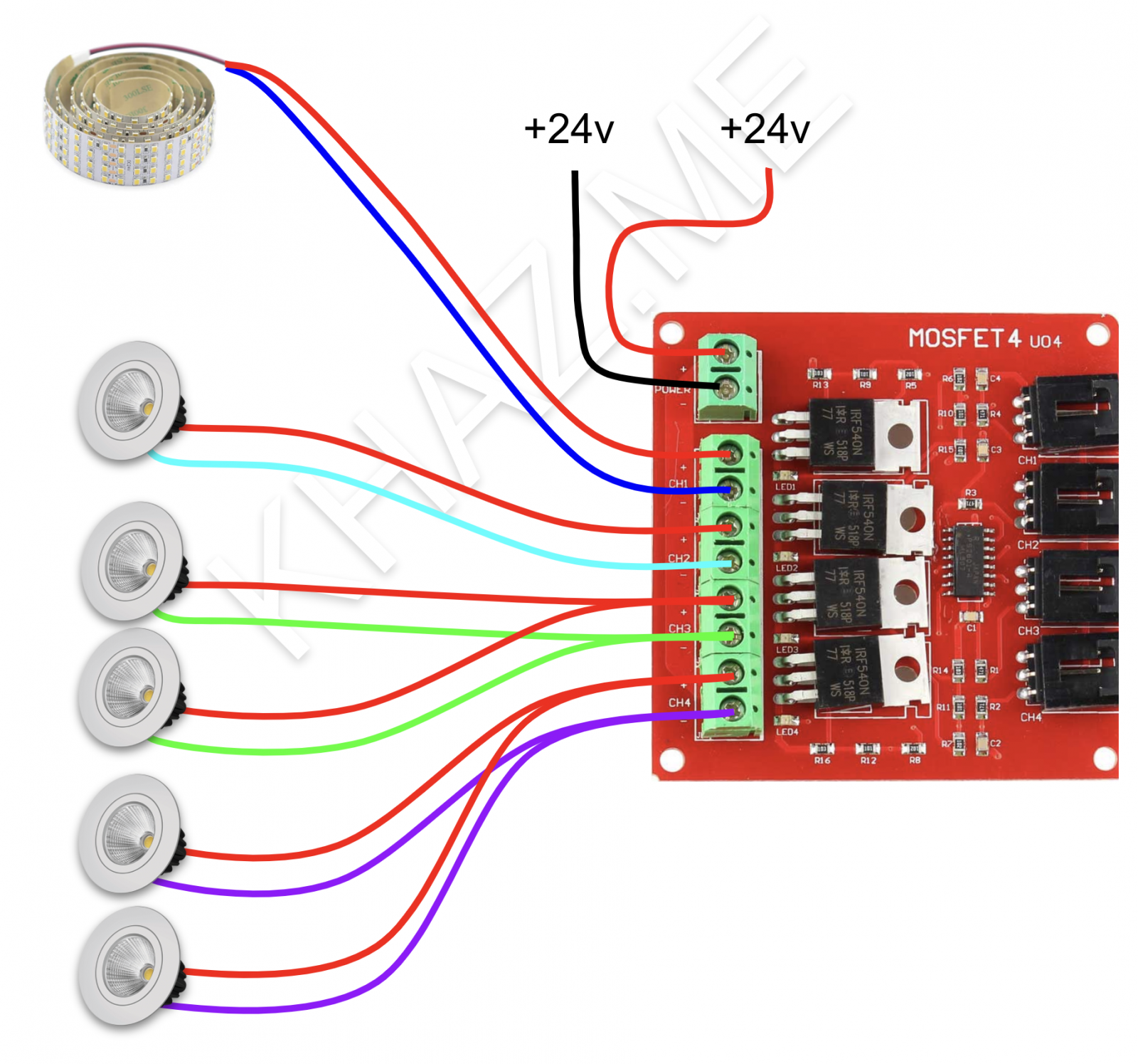
The wire types that you use are up to you. It’s important to select the correct wire for the LEDs based on the current draw and the distance you’re running. My longest wire are about 40 feet and there I used bell wire. For shorter 20ft runs with only one light I used cheap CAT6. The wires between the Wemos, PCA, and MOSFET were either dupont or servo extension.
Firmware
As you probably would have guessed, I used the trusty ESPHome project to create the firmware for the Wemos D1. This is pretty straightforward to configure. as you configure the PCA9685 as outputs per the documentation, and then just tie your lights to those outputs to lights.
|
1 2 3 4 5 6 7 8 9 10 11 12 13 14 15 16 17 18 19 20 21 22 23 24 25 26 27 28 29 30 31 32 33 34 35 36 37 38 39 40 41 42 43 44 45 46 47 48 49 50 51 52 53 54 55 56 57 58 59 60 61 62 63 64 65 66 67 68 69 70 71 72 73 74 75 76 77 78 79 80 81 82 83 84 85 86 87 88 89 90 91 92 93 94 95 96 97 98 99 100 101 102 103 104 105 106 107 108 109 110 111 112 113 114 115 |
substitutions: platform: ESP8266 board: d1_mini device_name: esphome_lvrc friendly_name: "LVRC" reboot_timeout_wifi: 900s reboot_timeout_api: 1800s output_power: 17dB gamma_correction: '1.6' led_max_power: '0.85' esphome: platform: ${platform} board: ${board} name: ${device_name} build_path: ./build/${device_name} wifi: ssid: !secret wifi_iot_ssid password: !secret wifi_iot_pwd fast_connect: on reboot_timeout: ${reboot_timeout_wifi} output_power: ${output_power} ap: ssid: "AP_${friendly_name}" password: !secret wifi_backup_pwd api: reboot_timeout: ${reboot_timeout_api} ota: web_server: port: 80 logger: captive_portal: switch: - platform: restart name: "${friendly_name} REBOOT" text_sensor: - platform: version name: "${friendly_name} ESPHome Version" i2c: - id: bus_a scl: D1 sda: D2 frequency: 100kHz scan: True pca9685: i2c_id: bus_a address: 0x40 frequency: 1000 output: - platform: pca9685 id: 'pca9685_output0' channel: 0 inverted: False max_power: ${led_max_power} - platform: pca9685 id: 'pca9685_output1' channel: 1 inverted: False max_power: ${led_max_power} - platform: pca9685 id: 'pca9685_output2' channel: 2 inverted: False max_power: ${led_max_power} - platform: pca9685 id: 'pca9685_output3' channel: 3 inverted: False max_power: 0.70 - platform: pca9685 id: 'pca9685_output4' channel: 4 inverted: False max_power: 0.70 light: - platform: monochromatic output: pca9685_output0 name: "Entry Outdoor" default_transition_length: 1s restore_mode: ALWAYS_OFF gamma_correct: ${gamma_correction} - platform: monochromatic output: pca9685_output1 name: "Entry Indoor" default_transition_length: 1s restore_mode: ALWAYS_OFF gamma_correct: ${gamma_correction} - platform: monochromatic output: pca9685_output2 name: "Foyer Hall" default_transition_length: 1s restore_mode: ALWAYS_OFF gamma_correct: ${gamma_correction} - platform: monochromatic output: pca9685_output3 name: "Stairs" default_transition_length: 1s restore_mode: ALWAYS_OFF gamma_correct: ${gamma_correction} - platform: monochromatic output: pca9685_output4 name: "Dining Outer" default_transition_length: 1s restore_mode: RESTORE_DEFAULT_OFF gamma_correct: ${gamma_correction} |
The components above include
- An I2C component to enable I2C communication
- A PCA9685 component to define the PWM module
- Outputs for each of the channels used on the PCA9685
- Lights for each of the Outputs
- A switch restart component to reboot the Wemos
Be First to Comment