Last updated on November 7, 2023
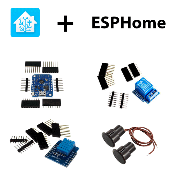
Home Assistant is the main method I use for opening my garage (other than the integrated remote in my car). I’ve had this setup for the better part of a year and thought I would share it in case it helps anyone else control their garage door. This hardware has been running with Tasmota firmware for the bulk of that time and recently I’ve discovered ESPHome and have converted this guy. And while there are plenty of DIY tutorials for garage door control, I think this is the simplest to get up and running. The parts list is very basic:
- Wemos D1 Mini – The Wemos D1 Mini is an ESP8266 based microcontroller that will handle the heavy lifting of WiFi and communicating to your Home Assistant instance [AliExpress | Amazon]
- Wemos Relay Shield – The Relay Shield will perform the physical function of closing the circuit on the garage opener to activate it [AliExpress | Amazon ]
- Wemos DHT shield – I added the DHT to get temperature and humidity data [AliExpress | Amazon ]
- Wired Reed Switch – A magnetic reed switch that will provide state of the door [AliExpress | Amazon ]
- LM2596S DC-DC power regulator – It converts garage door’s 12V DC to 5V DC for the Wemos or use a microUSB cable. [AliExpress | Amazon ]
I buy my stuff from AliExpress because it’s so cheap that it’s basically free as long as you can put up with month-long shipping. I think all of these combined were about 10 bucks. When you finally get these parts from China, you will need to solder the Wemos headers together so you can stack them. My relay shield was on GPIO5, the DHT shield was on GPIO2, and I connected the reed switch on GPIO13. My garage door opener has an option for a backup battery, and the connection for this battery provides a 12v DC output when the garage door opener is powered up. So while I could have powered the Wemos thought a micro USB and a wall wart, I just got the DC-DC power regular. I connected it to the garage door and used a multimeter to adjust it’s potentiometer to a 5v output and then connected the ground and 5v to the Wemos.

Installation is pretty straight forward, you connect the garage door opener’s control contact (same ones where your local button is wired) to the common and normally open contacts of the relay. I’ll eventually post some pictures, but I don’t have any right now.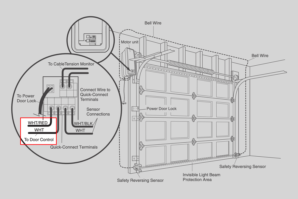
I’m not going to go through the details of setting up ESPHome. You can watch either Rob’s or digiblur’s videos to get a good explanation on it. Once you have it up and running, you will need to create a new device by populating the name and WiFi details. Here is my config:
|
1 |
esphome:
name: esphome_garage_door
platform: ESP8266
board: d1_mini
wifi:
ssid: 'insert'
password: 'your_own'
fast_connect: on
api:
ota:
web_server:
port: 80
logger:
binary_sensor:
- platform: gpio
pin:
number: GPIO13
mode: INPUT_PULLUP
inverted: False
name: "Garage Door Sensor"
device_class: garage_door
filters:
- delayed_on: 20ms
sensor:
- platform: dht
pin: GPIO2
temperature:
name: "Garage Temperature"
filters:
- lambda: return x * (9.0/5.0) + 32.0;
unit_of_measurement: "°F"
humidity:
name: "Garage Humidity"
update_interval: 60s
model: AM2302
switch:
- platform: gpio
id: relay
pin:
number: GPIO5
inverted: False
restore_mode: ALWAYS_OFF
- platform: template
name: "Garage Door Switch"
icon: "mdi:garage"
turn_on_action:
- switch.turn_on: relay
- delay: 1s
- switch.turn_off: relay
- platform: restart
name: 'Garage Door REBOOT'
status_led:
id: status_led
pin:
number: GPIO2
|
The components above include
- A binary sensor component for the reed switch input
- A sensor component for the DHT temp and humidity
- A switch gpio component for the relay
- A switch template for the pulsed output imitating a momentary button press
- A switch restart component to reboot the Wemos
- A status LED component for indicating networking/error status.
Now can compile the firmware and flash it to your Wemos D1. Again, if you’re not familiar with how to do this, reference the videos linked above. Once it’s flashed, power cycle the device. Now you should be able to open the web gui for the device by either going to it’s IP or going to esphome_garage_door.local in your browser. When the page loads up, you should test out the Garage Door Switch by hitting the button next to it. If when you open the Garage Door Sensor changes state, then everything is working as it should.
Now to integrate it into Home Assistant, you will need to go to configuration > integratios. Assuming you have discovery enabled, you will have a new ESPHome device, click configure and add it to your system. In theory, if you don’t have any existing conflicting entities, your entity names should match the ones I have (If not, post in the comments and I’ll try to help). I’m using lovelace with the following config:
|
1 |
- type: horizontal-stack
title: Doors
show_header_toggle: false
cards:
# I have other doors here
- type: entity-button
name: Garage
tap_action:
action: call-service
service: homeassistant.turn_on
service_data:
entity_id: switch.garage_door_switch
hold_action:
action: more-info
entity: binary_sensor.garage_door_sensor |
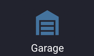
This provides you with a simple button who’s icon shows you the state of the door.
Because I’ve forgotten to close the door a few times, I’ve also set up an alert on the door to notify my phone when the door is open for more than 10 minutes:
|
1 |
alert:
garage_door:
name: Garage is open
done_message: Garage is closed
entity_id: binary_sensor.garage_door_sensor
state: 'on'
repeat: 10
can_acknowledge: true
skip_first: true
notifiers:
- your_ios_identifier |
A word about security. This setup means that anyone with access to your WiFi network could open your garage door. This would also assume the intruder is on your WiFi, knows the name or the IP of the device, the fact that it’s running a web server, and could connect to it to open your garage door. Personally, I tightly control the people that have access to my network so it’s not a big concern for me. The likely hood of that happening seems lower than someone breaking a window on my house.
[…] having played with an Arduino a couple of time for a robot project. For the most part I followed D Khaz’ page so I want to be sure to give credit where it is […]
Thanks for this! Works great! Does exactly what I needed it to do and the alert for door open is a great addition. There were a few changes I had to make to the ESPHome code and Lovelace card, but that’s more than likely due to the updates since your original design and wasn’t something too hard to figure out with some further research.
Do you have a photo of this thing put together? I’m decent with soldering and electronics, it was my job for a bit, but I haven’t used any of these pieces before and I can’t seem to follow.
I’m reading this part:
“…you will need to solder the Wemos headers together so you can stack them. My relay shield was on GPIO5, the DHT shield was on GPIO2, and I connected the reed switch on GPIO13.”
I have all of the parts in your list minus the DHT shield and I don’t have anything with those markings on it. The D1 Mini and the relay shield have (or a slight variation of) 5V, G, D4, D3, D2, D1, RX, TX, 3V3, D8, D7, D6, D5, D0, A0, RST.
Take a look at the this: https://photos.app.goo.gl/WQytydoJUvwzVVqTA
I’d probably recommend putting the DHT below the relay so it stays cool
[…] to Khaz.me for the guidance: https://khaz.me/cheap-and-easy-home-assistant-garage-door-control/ Be sure to also check out their link […]
Because that is what the documentation says.
I am very new to these boards so please forgive my inexperience. You say that you have your relay shield on GPIO5. How do you know which GPIO the relay is on when the stacked modules connect and touch all the pins? I’ve watched a couple videos on soldering these together, but no one seems to explain this.
@ar did you get yours working in Aus? Would love to hear how you worked with osc
@Andrew yep all works now. The relay hooked into the OSC bits of the opener without a problem. I used an old phone charger to power the Wemos.
Only other difference in what I did was define the switch as a cover. Can share yaml if you’re interested, it’s pretty straight forward.
Anonymous join the home assistant forums and post in the esphome section. Tag me in @nickrout and we’ll get it sorted!
hoping you can help with a coding question. I setup another d1 mini based on your garage door control but i want it to operate a light. the idea is to have a reed switch on d7. when the reed switch is closed the relay is off, when the reed switch is open the relay is on. i have the reed switch working but can not quite figure out the code for the relay. any help appreciated.
Yea, this is a breeze with ESPHome. You should add the reed switch as a binary input. Then follow the documentation for “on_state” under Binary Sensor Automation.
Not quite a breeze, have found about 300 ways to code it incorrectly. Will keep trying.
I can achieve the same result using a sonoff basic and node-red based on the status of the d1 sensor but trying to learn something new.
Post what you’ve put together with a pastebin link (full yaml) and I’ll take a look
Thanks, I have it working. The Home Assistant forum was able to review the code and advise. Thank you again for sharing this and your other projects.
@Nick Rout
I solved this last night shortly after posting. I hadn’t been aware that the Wemos D1 Mini can be flashed when plugged directly into the Micro USB port. This entire time, I’d been plugging my USB to UART bridge straight into the pin headers.
The latter method worked on my sONOFF Basic for a different use.
So all I did was plug the Wemos into the machine running ESPHome and flashed it straight from the web UI in the hass.io addon. Worked so well.
Everything works great and this was a great learning experience. Thanks to everyone involved in this thread and Khaz for the initial writeup!
Glad it all worked out!!
Are you sure it is COM6? Most computers have very few serial ports these days.
Why not use the computer you are running esphome on to flash?
Which board are you using? Are you sure it has a cp210x chipset and not something else?
So I’ve given this a fair crack, but stuck at flashing. Anyone ever experienced this error in the ESPhome flash tool?
Using ‘COM6’ as serial port.
Unexpected error: could not open port ‘COM6’: PermissionError(13, ‘Access is denied.’, None, 5)
I’ve installed the CP210x drivers on my Windows machine and I’m all out of ideas.
@AR “If I just use an old 5v phone charger and solder the power/gnd of a micro usb into the wemos, would that suffice?”
A wemos has a usb port and you can plug a phone charger in directly, No soldering required.
A couple questions:
– Can you recommend a case to enclose all this?
– If I just use an old 5v phone charger and solder the power/gnd of a micro usb into the wemos, would that suffice?
I used a double gang electrical box that I had lying around, although it would have fit in a single.
Update on Aus Garage Door, shorting OSC and ground performs the operation of opening, stopping and closing. Many thanks for the advice. I’ll continue on with this project. Now the waiting game while my parts arrive!
Very much appreciate your work here. Working great. Thank You.
Awesome!
@Nick Rout
Thanks so much for that, I’ll stick old some speaker wire into it and see what happens!
Damn I forgot to say, you can test it with a bit of hookup wire, just short out the terminals.
@AR that should work. This looks much like my controller (NZ). OSC means Open Stop Close – each time you short the terminals for a brief time, the door will cycle through those three modes, like when you press the remote a number of times.
Disregard the post, relay was bad. All is working now, thanks for posting this project!
Glad you got it working!
I can not get the relay to activate. Have tried stacking and wiring separately, even tried different relays and d1, none will work. I do not have the dht shield so I commented out that part of the code. Open/close is working and home assistant is sending the correct command, any idea why the relay is not responding?
Could be a bad relay. Or maybe the one you bought uses a different pin. You should be able to see the trace on the shield.
Try manually testing the relay by applying 5v and GND to labeled pins, and then temporarily touching 5v or ground to GPIO5. One of those should switch the relay depending on if it’s active low or high.
^ sorry, it was page 11, section 12.
Hi there,
I’m from Australia and I’ve got this door opener:
http://autoopeners.com.au/wp-content/uploads/2018/05/AO6v3-Roller-Opener-Manual.pdf
I see on page 12, I have some pins to tap into. Do you think your solution would be compatible?
Cheers mate
As long as the garage door is initiated by closing or opening a circuit, this solution will work. I didn’t see a wiring diagram, but you can also solder to the wires of the wireless remote button. This will mean you will have Home Assistant “pressing” your remote button.
Have you had any false open or close with the Wemo D1? If you lose power or wifi does it trigger the relay on startup?
You can depending on how your Wemos vs the relay is powered and if you have pull up/down resistors. Personally I tested to make sure I didn’t have this problem. There are also some pins on the Wemos that go high/low during boot that should be avoided.
No, I don’t have any issues with it. Just make sure your system behaves as expected on reboots in terms of pull up/down resistors
Nice write up and just what I have been about to do for months now, perhaps with your prompt I will get to it now.
One question though, is there a reason that you didn’t use the cover component in esphome?
Thanks. It’s much easier than it sounds. I put on audible book and managed to get it done while cleaning the garage in a few hours.
I’ve been using this since “format” for my garage door for over a few years. And when initially made it, covers were new and didn’t have good support anywhere. It was well before Lovelace and I found this template approach the best way to give me what I wanted.
Today, covers *should* have much better support and can probably do this as well, but this just works so I haven’t spent at time updating it.
Do you have a case or container to keep the final result in? Something to protect it a little or hide some of the components? Any recommendations?
I screwed some terminal blocks to a small piece of wood and hot glued the Wemos to it. It’s not the prettiest hardware, but it’s very effective.
Was this designed for NO or NC reed switches?
It will work with both with a little tweak in the yaml
Hello,
I’d first like to thank you for publishing this it has been very helpful.
I have two garage doors which I am using a SM-226-3Q Seco-larm Overhead door Mount N.C. Magnetic Contact w/3 wire for N.O. and N.C application both of the reed switches are mounted at the same location on the two different doors and hooked to the same pins on two different NodeMCUs. running on the same coding for the door sensor code you have written above. When the door is closed the the switch is closed and applies voltage to the sense pin GPIO15 (D8). One door the door position sensor works perfectly and the other door the door indicator shows that the door is closed OK but when the door opens the door position indicator on Hassio shows the door open closed, open closed the entire time the door is open. I have tried applying 5 volts to the reed switch, I’ve also tried other sense pins I’ve tried replacing all the components and no matter what I do it does it. Currently the door sensor is disconnected and the indicator on Hassio shows it is open closed open closed over and over. Any thoughts?
Also can you tell me what yaml. you have this in and where it is placed exactly?
Thank you in advance for your time.
– type: horizontal-stack
title: Doors
show_header_toggle: false
cards:
# I have other doors here
– type: entity-button
name: Garage
tap_action:
action: call-service
service: homeassistant.turn_on
service_data:
entity_id: switch.garage_door_switch
hold_action:
action: more-info
entity: binary_sensor.garage_door_sensor
H John,
Sounds to me like it’s possibly a floating pin.
Try this:
– Put a jumper into D8, and connect it to Vcc – Look at the web server for the device and confirm it shows the door as closed without any bounce
– Put a jumper into D8, and connect it to GND – Look at the web server for the device and confirm it shows the door as open without any bounce
If that’s the case, take a 5k resistor and add to the circuit: one leg to the D8 pin, the other to GND.
That part goes into your lovelace ui file. If you are not doing manual yaml config, you have to edit it through the GUI and then select the show raw config. Google the type of card to get more info on it.
After a bit of research, I’m going to try a beam sensor like this:
https://s.click.aliexpress.com/e/bPO8vN84
Which I think uses this in esphome:
binary_sensor:
– platform: …
device_class: safety
I have also purchased a 2pin wire to 2x DC 5.5*2.1mm power jacks cable to power the beam sensors (12vdc) and D1 Mini (via wemos power shield 12vdc to 5vdc) from the garage door unit (12vdc output).
Wish me luck and I’ll let you know how it goes.
You’ve got powering the sensors covered. Did you also get connectors and cable for the light beam signal?
What device are you bringing them into and on what pins?
Otherwise sounds like a good plan.
You might want to see if the interlock function in ESPHome will prevent your from activating the garage door relay while the beam is blocked.
To be honest, I’m a newbie to this so need to do a fair bit more research. I’ve now received the beam sensors and some other parts. I’ll try to put all the details up here if I manage to get it to work.
Are the safety sensors part of your garage door model?
Any ideas for integrating a sensor as part of the project to tell home assistant whether there are any objects blocking the door before closing?
The photocell along the bottom of the garage door is part of the garage door’s safety system. I don’t think there is any use for it to be integrated into HA. That system remains isolated to the garage door system itself and HA is basically just asking it to open or close. This is a safer way to approach the design as any failures within the Wemos won’t break the garage door system, it will just mean I can’t control it through HA.
If you really wanted to add it, you can probably bring it in as a separate binary sensor and then make some basic interlock logic. But again, not my recommendation, and it’s pretty cheap and easy to add an additional photocell (https://amzn.to/307FalA) rather than messing with the one that’s already part of your garage.
Thanks.
Sounds like I’m on the right track.
The beam sensors for my garage unit cost about $60 and I’d rather get less expensive ones like you linked to. However, I’m not sure if they can be used directly with my garage door unit and would prefer that if they stop working, it doesn’t interfere will normal operation of the garage door.
By running them through HA, if the beam sensor stops working correctly and/or the wemos breaks down, I’ll just be prevented from closing the door via WiFi and the remote controls will continue to operate normally.
I think you can just set it up as a condition of activating the switch for the garage door.
How accurate is the AM2302 with the D1 shield? I’ve tried the ESP-01 DHT11 shield and the ESP generates enough heat that the data is garbage.
Yea, It’s pretty much garbage. I just looked at the past 24 hours of data and it ranges from 74-82 while it’s 60 degrees outside. My furnace is right next to it so I’m sure it’s contributing to the shitty data.
It’d be easy enough to extend the temp sensor out via a few feet of wire to eliminate thermals from the Wemos. I might have to do it, but I just haven’t found the need for this data as it never freezes here.
This is a great write up. I’m currently using a Sonoff 4ch pro with ESPhome to control both my garage doors. It worked perfectly for the first month but recently one of the relays started firing randomly so I had to move it to one of the two open relays. Have you seen this at all with the wemos?
Personally, I only have great things to say about it. I’ve got them running in several places and they have been rock solid. And I’m loving ESPHome, Otto is doing an incredible job!